Nowadays, the fourth-generation products, featuring compact, modular, intelligence and communication, have drawn great interest from the industry and face opportunities of rapid growth.
As core component of electric switches and instruments,
contact materials play a major role in making, braking circuits and loading current, thus affect the performance of electrical apparatus directly, Therefore the evolution of Low-Voltage Electric Products and Electronics Products calls for continuous and fast improvement of the contact material.
AgWC is widely used as major moving contact material in the fourth-generation Circuit Breakers for its much better electrical capability compared with
AgW material adopted in the third-generation products. It is also the most potential moving contact material for future improvement.
So, the optimal route should be the enhancement in anti-erosion ability of AgWC material by improving its manufacture process. In this work, we introduce two new types of AgWC material fabricated through modified manufacturing process, and it is showed that the difference in microstructure determines greatly their anti-erosion ability.
1. Experiment
- Manufacture of the AgWC40 sample:
Firstly, the AgWC skeleton powder was prepared by mixing Ag and WC powder together. The powder was then granulated and compacted into AgWC skeleton. After that, the infiltration progress was conducted to the pre-sintered skeletons with silver plate on top. The products were re-pressed, washed and polished before testing.
In this work, the main difference between manufacture processes of the two samples lies in the powder mixing process:
The chemical mixing: WC powder was dissolved into AgNO3 solution under fierce string. Then, Ag was precipitated on WC particle gradually after the adding of reductant to form AgWC skeleton powder.
The physical mixing: We and Ag powder were mixed in a mixer for about 6 hours to form the AgWC skeleton powder.
- Characterization and Electrical performance test of the sample:
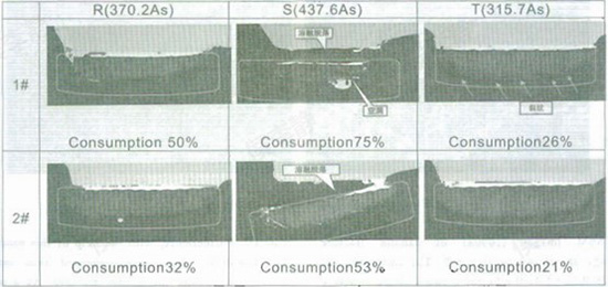
The metallographic pictures were taken by a Nikon ECLIPSE L150 microscopic. The projected images were taken by a Yixin EV2515 projector. A JEOL JSM-6390A scanning electron microscopic was used to check the fracture morphology, and a SANS-CMT universal testing machine was used to measure the fracture resistance. The electrical performance test were conducted under the test condition of 440V/18KA, with a test routine O-t-O-t-O. The energy of phase R, S and T is 370.2As, 437.6As and 315.7As respectively.
2. Results and Discussion
We mark the chemical mixing sample as sample 1, and physical mixing sample as sample 2 in this paper.
- Metallographic Structures:
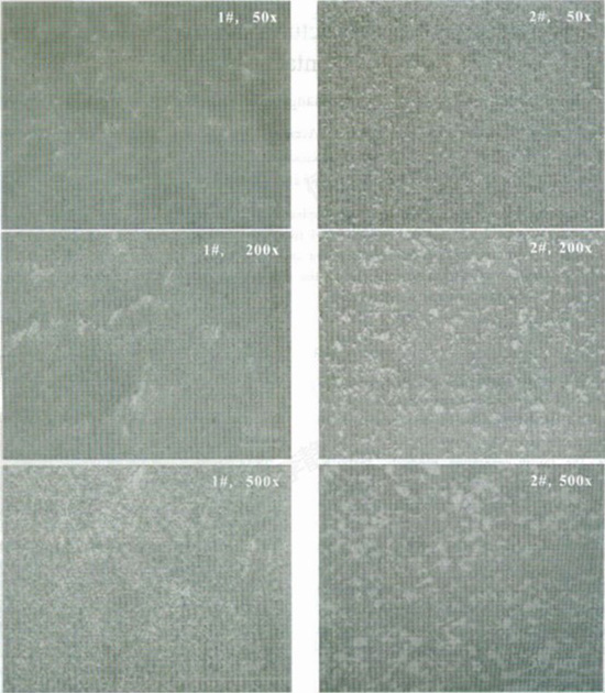
The two mixing processes mentioned above lead to different microstructures, as shown in figure 1.
Figurel Metallographic images at different magnitudes ofthe two samples
It could be seen from the 50x images that sample 1 shows a non-homogenous metallographic structure, in which the global microstructure is divided into several areas by the silver agglomeration "border", whereas sample 2 shows an uniform metallographic structure without any divided areas.
However, as the magnification of the microscope increases to 200x and 500x, metallographic structure in the micro-domain of sample 1 becomes homogenous with no significant Ag aggregation nor WC aggregation. On the contrary, different shapes of aggregations larger than 10μm of Ag and WC are observed in the metallographic of sample 2.
We attribute the above difference to the different powder mixing processes:
On the one hand, Ag is precipitated on each WC particle to form silver layer in the chemical mixing process, which leads to a homogenous distribution of the WC among Ag background in the micro-domain structure without any obvious aggregation. Nevertheless in this process, a tight joint is introduced between Ag and WC particles and also the distribution of W among Ag background becomes much too uniform, thus Ag is bounded around WC, while its flowability dramatically decreases as a result. Shrinkage occurs in the subsequent processes such as pelletization and pre-sintering, in which Ag could not act as buffer due to its lack of flowability, thus the skeleton experiences an inhomogeneous shrinkage stem from the thermal mismatch and unequal stress distribution and derives a microstructure with different"areas". Moreover, pore channel among the skeleton is too narrow for the flow of Ag, therefor restricts WC particles from re-arrangement in the infiltration process, and keeps those "areas” in the final structure of the sample.
On the other hand, physical mixing offers much less homogenous AgWC skeleton powder than chemical mixing, and due to its large surface energy, WC particles tend to aggregate in the mixing process. As a result, WC aggregations together with Ag aggregations occur in the micro-domain structure of sample 2, which derive much better flowability of Ag. The freely flowing Ag becomes buffer when the skeleton meets with thermal mismatch and unequal stress distribution in the pelletization and pre-sintering process. Especially when infiltrating significant particle re-arrangement takes place due to the spacious and smooth pore channel, thus induces homogenous distribution of the WC aggregations among entire structure.
Electrical properties of the two AgWC40 samples were evaluated, The consumption data of each contact after electrical test are presented in table 1. It could be seen that the consumption of sample 2 are less than that of sample 1 at each phase, which denotes sample 2 possesses better anti-erosion capability.
Table 1 Residual content of two samples after electrical test (440V/18KA, O-t-O-t-O)
We suppose this difference in anti-erosion capability originates from the difference in microstructures.
As discussed above, in the case of chemical mixing, the pore channel in skeleton is too narrow for the flow of Ag in the process of infiltration. Furthermore, Ag does not wet WC so well. As a result, Ag fails to infiltrate through the microstructure thoroughly, therefore cannot form a connected network and derives a loose microstructure. This kind of microstructure can easily be damaged by the high-energy arc and shows poor anti-erosion capability.
However, physical mixing enhances the flowabilily of Ag: in the case of physical mixing, widespread Ag aggregations exist in the structure, which denotes the existence of connected spacious pore channel. As a result, Ag could flow freely through the skeleton, and the Ag plate beneath could easily enter the skeleton after melting through widespread pore channel. With the homogenously distributed Ag and WC aggregation, every micro-domain is equivalent to a micro-infiltration system: the Ag aggregation provides the WC aggregation with Ag for infiltration whereas gets supply from the beneath Ag plate through the pore channel. As a result, Ag infiltrates thoroughly through the entire skeleton and forms a connected network, thus enhance the internal bond and then the anti-erosion capability of the material.
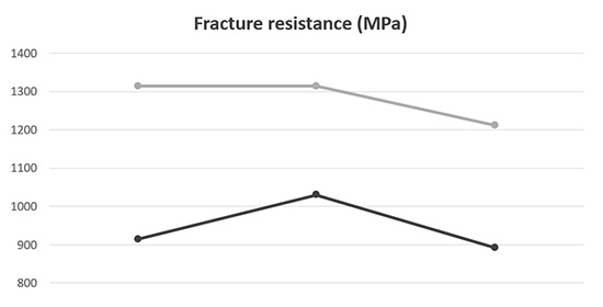
Figure 2 Fracture resistance ofthe two samples
Fracture resistance and fracture morphology of the samples were characterized to demonstrate the above analysis.
The fracture resistance of sample 2 is much larger than that of sample 1 (shown in Figure 2). As is widely accepted, the fracture resistance reflects the internal bond status of a material. Therefore the internal bond in sample 2 should be better than that in sample .
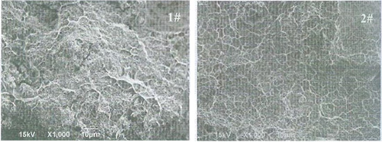
Figure 3 SEM images of the sample fractures
The SEM images (1000x) of sample fracture morphology are shown in Figure 3. The tiny spherical particle is WC, while the bright network shape structure is Ag. In sample 1, the Ag network is fragmentary and non-continuous, and WC particles expose on the fracture surface, infer that Ag failed to infiltrate thoroughly through the structure. However in sample 2, a connected Ag network could be clearly observed, also WC particles are vanished because of the cover of Ag, denote that Ag is almost infiltrated though the entire structure.
3. Conclusion
Two types of AgWC40 material were manufactured through different processes. One material shows better anti-erosion ability in the electrical test than that of the other. Analysis infers that the physical powder mixing process results in more homogenous microstructure of the material. Furthermore, with the help of this process, the Ag flowability is greatly enhanced thus infiltrated thoroughly through the entire structure. As a result, a connected Ag network is formed therefore increased the internal bond and then the anti-erosion ability of the material.