Posted on 10/26/2026 by Fudar Offical | Views: 153
A molded-case circuit breaker (MCCB) protects electrical circuits against overloads and short circuits. Inside the breaker, the moving contact must be securely joined to its copper support. A weak joint can lead to premature failure of the contact assembly.
Fudar studied resistance spot welding to join silver tungsten (AgW) contacts to copper without adding brazing filler metal. The process uses the contact's existing silver layer to form the bond.
This article explains how the joint forms and how welding current, time and pressure affect its strength.
AgW combines good electrical and thermal conductivity with resistance to wear and arc erosion. These properties make it useful for MCCB contacts. However, joining it securely to copper can be difficult.
Common joining methods include resistance brazing and induction brazing. Both use a filler metal that melts and flows between the parts to form a joint. Our study examined whether resistance spot welding could produce a strong joint without adding brazing filler metal.
We tested AgW65 contacts and TU2 oxygen-free copper bridges. Each contact had a silver layer approximately 0.05–0.2 mm thick on its joining surface. This surface also had three raised, tooth-shaped features.
During welding, current flowing through the parts generates heat where they meet. The silver layer and copper combine locally to form an Ag–Cu alloy, helping bond the parts together.
Pressure also holds the parts together and changes their shape. The contact becomes partly embedded in the copper bridge. Both this change in shape and the alloy formation contribute to joint strength.
The process needs a balance of heat and pressure to form a strong bond while retaining enough silver at the joint. We examined three factors: welding current, welding time and welding pressure.
| Welding parameter | Effective range |
| Current | 7.8–8.0 kA |
| Time | 180–200 ms |
| Welding pressure | 0.25–0.4 MPa |
These ranges apply to the parts and equipment used in this study. We varied one parameter at a time while holding the other two constant. Other assemblies require separate validation.
Current affects how much heat is generated. Too little current may not provide enough heat to form a strong bond. Too much can cause silver loss and, in severe cases, contact damage or cracking.
Welding time determines how long heat is supplied. A welding time that is too short provides too little heat for a strong bond. One that is too long can overheat the joint and cause silver loss.
Pressure keeps the parts in contact during welding. Too little pressure can cause localized overheating and sparking. Too much can squeeze silver out of the joint, making it harder to bond the contact to the copper.
We randomly selected 10 assemblies containing 20 contacts for shear testing. This test measures how much sideways force is needed to separate the contact from the bridge. The measured shear forces ranged from 1,923 to 2,488 N.
We also examined a cross section of the joint under a microscope. It showed the contact embedded in the copper bridge, with no obvious gap between the two parts, as shown below.
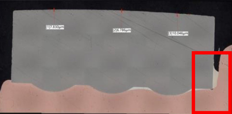
Figure 1. Cross section of the welded contact and copper bridge.
After shear testing, copper remained on the separated AgW contact, while silver remained on the copper bridge. Analysis of the joint and nearby areas also detected both silver and copper. Together, these findings were consistent with the formation of an Ag–Cu alloy at the joint.
The assemblies also met the customer's requirements in circuit-breaker interruption tests, which assess the breaker's ability to interrupt current.
For the AgW65 and copper assembly tested, resistance spot welding produced strong joints without adding brazing filler metal. The process also lends itself to automated production.
The results show why contact design and welding conditions need to be considered together. Keeping enough silver at the joint and balancing heat and pressure were essential. For other contact designs, the process should be validated through joint testing and the relevant circuit-breaker tests.
If you have any questions about contact assemblies for MCCBs, please feel free to contact us.
Please fill out the form below. Our sales team is ready to assist you with any questions or inquiries.

