AgSnO₂ is widely used for relay contacts because it offers a useful combination of conductivity, resistance to welding, and resistance to arc erosion. However, the chemical composition alone does not determine performance. The size and distribution of oxide particles, together with hardness and additive content, also affect how the contacts behave during switching.
The study summarized here compared a conventional AgSnO₂ material with a modified formulation under the same automotive lamp-load conditions. The modified material achieved approximately 60% higher characteristic life in the simulated contact test and 46% higher characteristic life in complete relays. The results help explain why material design must be matched to the actual relay load.
What Did the Study Compare?
Both materials were produced by internal oxidation, processed into 1.4 mm
silver alloy wire, and cold-headed into contact rivets. Both contained 85.5 wt.% Ag and 4 wt.% In₂O₃, with SnO₂ accounting for the balance. They used the same additive system, but the modified material contained 2 wt.% additives, compared with 1 wt.% in the conventional material.
The
contact rivets were evaluated in a simulated contact test and in complete automotive relays under the same 13.5 V lamp-load profile. The main test conditions and failure criteria are summarized in Table 1.
Table 1. Key electrical test conditions
| TEST PARAMETER |
CONDITION |
Load profile
|
Simulated automotive lamp load
|
Voltage
|
13.5 V DC
|
Current
|
90 A inrush; 20 A steady state
|
Switching cycle
|
1 s on / 1 s off; operated to failure
|
Failure criteria
|
Simulated test: welding force above 30 g for five consecutive operations. Relay test: voltage drop above 1.35 V.
|
What Changed in the Modified Material?
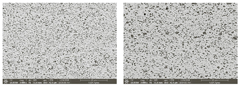
Scanning electron microscopy showed a clear difference between the two materials. Most oxide particles in the conventional material were smaller than 1 µm. The modified material contained a higher proportion of larger particles, including particles around 1 µm.
(a) Conventional AgSnO₂, 3,000× (b) Modified AgSnO₂, 3,000×
Figure 1. SEM microstructures of the conventional and modified AgSnO₂ materials at 3,000×.
This change in particle distribution altered the balance of material properties. The conventional material was harder and stronger. The modified material was softer but more ductile, with elongation increasing from 17% to 25%. It also showed slightly lower electrical resistivity, indicating slightly better conductivity. Density remained the same.
Table 2. Mechanical and physical properties of the two AgSnO₂ materials.
| PROPERTY |
CONVENTIONAL |
MODIFIED |
Hardness (HV0.3)
|
120.7
|
101.3
|
Tensile strength (MPa)
|
382
|
330
|
Elongation (%)
|
17
|
25
|
Electrical resistivity (µΩ·cm)
|
2.47
|
2.40
|
Density (g/cm³)
|
9.75
|
9.75
|
For relay contacts, higher hardness is not automatically better. A harder contact can rebound more strongly when it closes. Each rebound briefly separates and reconnects the contact surfaces, creating additional opportunities for arcing. Under the conditions in this study, the lower hardness of the modified material helped the contact pair close more steadily.
Longer Life Under the Same Lamp Load
Five tests were conducted for each material in both test formats. Lifetime analysis showed the same performance trend in both test formats, with the modified material lasting longer in each case.
In the simulated contact test, characteristic life increased from 146,573 operations for the conventional material to 234,856 operations for the modified material, an improvement of about 60%. In complete relays, characteristic life increased from 174,153 to 254,698 operations, or about 46%.
Table 3. Characteristic life in operations. Values in parentheses are 95% confidence intervals.
| TEST FORMAT |
CONVENTIONAL |
MODIFIED |
GAIN |
Simulated contact test
|
146,573 (139,585-153,908) |
234,856 (230,279-239,977) |
+60.2%
|
Complete relay test
|
174,153 (167,314-181,272) |
254,698 (250,795-258,661) |
+46.2%
|
The agreement between the two test methods is important because a simulated contact test cannot replace validation in the final relay. In this case, however, both methods showed the same overall trend, providing stronger evidence that the modified material offered a real performance advantage under the tested lamp load.
The study used a limited number of tests, so the exact lifetime values apply only to the materials and conditions evaluated. They should not be treated as guaranteed service life for every relay design or operating environment.
Why Did the Modified Material Last Longer?
The improvement can be explained by a simple chain of events. Because the modified material was softer, the contacts absorbed more of the closing impact. They bounced fewer times and therefore had fewer opportunities to separate and produce another arc immediately after closing.
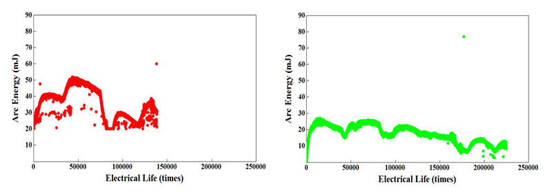
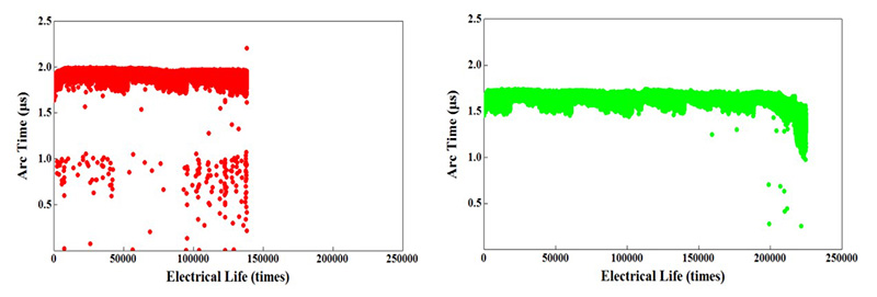
The arcs that did occur were also less severe. During most of the simulated test, the modified material showed lower arc energy and shorter arc duration. Welding force was about 0.04 N lower for much of the test. The main differences are summarized in Table 4, while Figure 2 shows how arc energy and duration changed throughout the test.
Table 4. Typical switching behavior during most of the simulated contact test.
| SWITCHING INDICATOR |
CONVENTIONAL |
MODIFIED |
Contact bounce
|
Typically 4-9 rebounds
|
Typically 0-6 rebounds
|
Arc energy
|
About 20-50 mJ
|
About 10-30 mJ
|
Arc duration
|
About 1.7-2.0 µs
|
About 1.5-1.75 µs
|
(a) Conventional - arc energy (b) Modified - arc energy
(c) Conventional - arc duration (d) Modified - arc duration
Figure 2. Arc energy and duration of the conventional and modified AgSnO₂ materials.
In simple terms, the modified material followed a more favorable chain of behavior: a softer contact material led to less bounce; less bounce reduced additional arcing; and lower arc severity slowed surface damage. This did not eliminate wear, but it delayed the point at which damage began to destabilize switching.
What Did the Contact Surfaces Reveal?
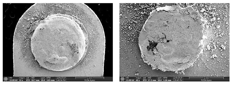
The post-test surfaces showed that the two materials did not simply wear at different rates. They developed different types of damage.
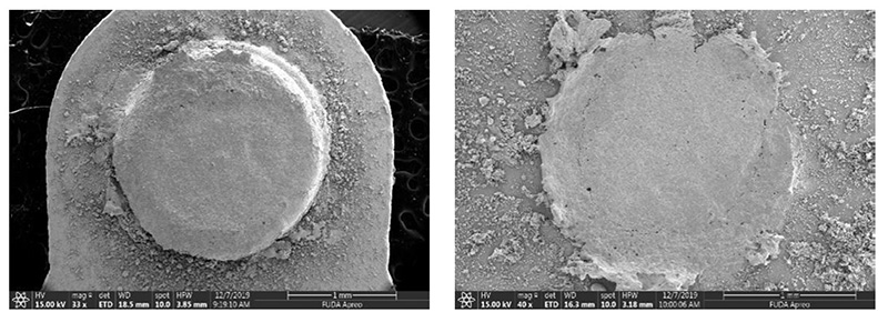
In the conventional material, material moved from the stationary contact to the moving contact. This created a raised deposit on one side and a matching pit on the other. The rough, uneven surfaces made the contacts more likely to weld together, which became the main cause of failure.
The modified material showed less directional transfer. Material loss occurred mainly on the stationary contact and was spread more evenly across the contact area. The surface remained comparatively smooth instead of forming the same pronounced deposit-and-pit pattern. This helped delay contact welding, although wear continued to accumulate.
(a) Conventional - moving contact (b) Conventional - stationary contact
(c) Modified - moving contact (d) Modified - stationary contact
Figure 3. Post-test contact surfaces at failure: conventional material, 138,260 operations; modified material, 224,795 operations.
In the simulated test, welding force for the modified material began to rise after approximately 100,000 operations and increased rapidly beyond 200,000 operations. Final failure was associated with accumulated material loss from the stationary contact and welding force exceeding the test limit. The modified material therefore extended the time to failure, but it did not prevent damage indefinitely.
What Does This Mean for Relay Design?
The results point to three practical lessons for automotive and other high-inrush DC relay applications:
- Design for the load profile. A material that performs well under one load may not offer the same balance under another. Lamp loads place particular importance on contact stability and anti-welding performance.
- Higher hardness does not always mean longer life. In this test, the softer modified material absorbed more of the closing impact, reducing bounce and the additional arcing that can follow.
- Material selection should balance several properties.Conductivity, hardness, contact stability, erosion resistance, and anti-welding performance must be balanced for the application's actual switching conditions.
Conclusion
Under the tested 13.5 V automotive lamp load, the modified AgSnO₂ material delivered longer electrical life, lower arc energy, shorter arc duration, and less severe material transfer than the conventional material. Its higher additive content, coarser oxide-particle distribution, and lower hardness were associated with more stable contact operation and a different pattern of surface damage.
The broader lesson is straightforward: the best
electrical contact material is not simply the hardest or most conductive option. Reliable performance comes from balancing composition, microstructure, and mechanical properties for the actual load. For lamp-load relays, reducing bounce and limiting arc severity can be just as important as the material's basic conductivity.
Optimizing contacts for a high-inrush relay application?
Talk with the Fudar Alloy team about AgSnO₂ materials, contact rivets, and application-specific electrical contact solutions.
Contact us.