As contactors become more compact and electrical endurance requirements increase, their
contact materials must withstand higher currents and tens or even hundreds of thousands of switching operations. Under these conditions, contact welding, material transfer, arc erosion, and surface cracking can all lead to premature failure.
Silver–nickel (AgNi) is widely used in low-voltage switching devices because of its good electrical conductivity, stable contact resistance, resistance to arc erosion, and suitability for high-volume production. However, conventional AgNi10 and AgNi12 may not provide sufficient durability for modern
HVAC contactors with higher current ratings and longer service-life requirements.
Increasing the nickel content may appear to be a straightforward solution, but testing shows that
more nickel does not necessarily deliver better overall performance.
The Trade-Off Behind Higher Nickel Content
Nickel has a much higher melting point than silver. Increasing its proportion in an AgNi material can therefore improve resistance to melting and contact welding.
However, higher nickel content also affects other properties:
- Electrical resistivity increases
- Hardness and tensile strength rise
- More force may be required to open welded contacts
- The material may become more susceptible to surface cracking and porosity under repeated arcing
The optimum formulation must therefore balance welding resistance, conductivity, mechanical strength, arc stability, and erosion behavior rather than simply maximizing nickel content.
Comparing Different AgNi Formulations
A comparative study evaluated six AgNi formulations with different nickel contents and trace additives.
Compositions of the AgNi Contact Materials (wt.%):
| Sample |
Ni |
T₁ |
T₂ |
Ag |
| 1# |
10 |
0.5–1.0 |
0 |
Balance |
| 2# |
12 |
0.5–1.0 |
0 |
Balance |
| 3# |
15 |
0.5–1.0 |
0 |
Balance |
| 4# |
17 |
0.5–1.0 |
0 |
Balance |
| 5# |
20 |
0.5–1.0 |
0 |
Balance |
| 6# |
15 |
0.5–1.0 |
0.3–0.5 |
Balance |
T₁ is a wetting-promoting additive designed to help molten silver spread more evenly and suppress the formation of cracks and voids. T₂ is a brittle additive designed to reduce the mechanical strength of welded junctions, making the contacts easier to separate.
All six materials were produced using the same powder mixing, sintering, extrusion, and wire-drawing processes. They were then formed into
rivet contacts of identical dimensions.
The simulated electrical test conditions were:
- Voltage: 220 VAC
- Current: 30 A
- Load: Resistive
- Operating frequency: 1,200 operations/hour
- Duty cycle: 20%
- Contact Force: 0.98 N
- Test stages: 50,000 and 100,000 operations
Performance was evaluated based on electrical resistivity, hardness, tensile strength, contact mass change, arcing energy, weld break force—the force required to open welded contacts—and surface morphology after testing.
Because the laboratory test used a resistive load, it served primarily as a controlled comparison of the different formulations. Component-level validation under application-specific compressor switching conditions was therefore still required.
Key Findings
All six samples completed 50,000 switching operations without contact failure.
Contact Mass Loss, Weld Break Force, and Arcing Energy after 50,000 Operations:
| Sample |
Movable Contact Mass Loss
×10⁻³ g |
Stationary Contact Mass Loss
×10⁻³ g |
Mean Weld Break Force
×(9.8 × 10⁻³) N |
Maximum Weld Break Force
×(9.8 × 10⁻³) N |
Mean Arcing Energy (mJ) |
Maximum Arcing Energy (mJ) |
| 1# |
−0.5 |
1.1 |
8 |
212 |
976 |
2,695 |
| 2# |
0.7 |
1 |
8.8 |
202 |
1,127 |
2,605 |
| 3# |
0.3 |
0.8 |
9.9 |
207 |
1,063 |
2,652 |
| 4# |
1.7 |
2.1 |
11.33 |
200 |
1,189 |
3,301 |
| 5# |
2.1 |
2.8 |
13.91 |
177 |
1,321 |
3,769 |
| 6# |
0.2 |
0.9 |
8.1 |
173 |
1,049 |
2,599 |
Note: A negative mass-loss value indicates mass gain caused by material transfer.
Lower Nickel Content Increased Welding Risks
The AgNi10 formulation showed a relatively small melted surface area and low apparent erosion after 50,000 operations. However, the movable contact gained weight because material had transferred from the stationary contact.
This indicated that the lower-Ni material entered a molten state more readily. During contact opening, molten material from the stationary contact adhered to the movable contact.
A relatively smooth contact surface or low apparent mass loss does not therefore necessarily indicate better performance. Material transfer can reveal an underlying welding risk that may eventually lead to contact sticking.
During the extended 100,000-operation test, the AgNi10 formulation ultimately failed because of insufficient welding resistance.
Excessively High Nickel Content Caused Cracking and Unstable Arcing
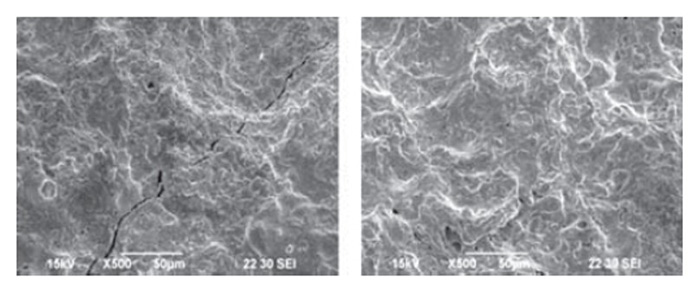
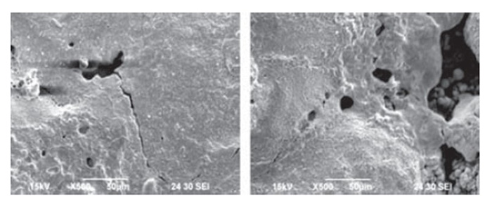
Formulations containing approximately 17%–20% nickel developed more visible surface cracks and pores after repeated switching. The 20% Ni formulation showed the most severe cracking.
SEM Images of Sample 4 Contact Surfaces after 50,000 Operations (500×)
SEM Images of Sample 5 Contact Surfaces after 50,000 Operations (500×)
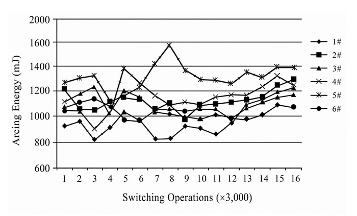
These defects can impede arc movement across the contact surface, increasing the likelihood of arc restrikes or sustained arcing. The high-Ni formulations showed a sharp rise in arcing energy as testing progressed.
Arcing Energy Trends during the 50,000-Operation Test
They also experienced greater erosion and higher weld break forces. During the 100,000-operation test, the 20% Ni formulation failed earliest because surface cracking and repeated arcing accelerated contact deterioration.
These results demonstrate that increasing nickel content alone does not guarantee longer electrical endurance.
Approximately 15% Nickel Provided the Best Overall Balance
Among the tested materials, a formulation containing approximately 15% nickel provided a better balance between welding resistance and arc stability.
Adding a small amount of a brittle material further reduced the mechanical strength of temporary welded junctions. Compared with a similar formulation without the additive, the optimized material produced a lower and less variable weld break force.
It also showed the lowest variability in arcing energy, indicating more consistent switching behavior. The optimized formulation completed 100,000 simulated operations without contact failure.
Results of the Extended Electrical Endurance Test (Target: 100,000 Operations):
|
Sample 1 |
Sample 5 |
Sample 6 |
| Operations Completed |
96,087 |
78,609 |
100,000 |
| Failure Mode |
Welding Failure |
Sustained Arcing/Short Circuit |
None |
| Test Result |
Failed |
Failed |
Pass |
Validation Under AC-8b Conditions
The optimized AgNi formulation was subsequently evaluated by several HVAC contactor manufacturers under more application-specific conditions:
- Rated operational current: 25 A
- Utilization category: AC-8b
- Required electrical endurance: 100,000 operations
The material successfully completed the required electrical endurance tests.
In previous trials under comparable conditions, lower-Ni reference materials experienced contact sticking or other failures after approximately 60,000–80,000 operations. The optimized formulation therefore provided a more reliable balance of welding resistance, arc stability, and long-term durability.
What Does This Mean for AgNi Material Selection?
The study provides three practical lessons for HVAC contactor design:
1. Optimize nickel content rather than maximizing it.
Insufficient nickel can increase welding and material transfer, while excessive nickel can promote cracking, unstable arcing, and higher weld break forces.
2. Evaluate composition together with additives, microstructure, and processing.
Even a small amount of an additive can significantly affect how welded junctions form and separate. Average erosion data alone may not reveal material transfer, surface cracking, or fluctuations in switching performance.
3. Validate the material under actual application conditions.
Current rating, utilization category, contact force, contact geometry, operating temperature, and target electrical endurance should all be considered during material selection.
Conclusion
For the HVAC contactor application evaluated in this study—with a rated current of approximately 25 A and a target electrical endurance of 100,000 operations—an AgNi formulation containing approximately 15% nickel provided the best overall performance.
Adding a small amount of a brittle additive further reduced weld break force and improved switching stability, enabling the material to complete both simulated endurance testing and subsequent AC-8b validation.
These findings are application-specific, but they highlight a broader principle: reliable AgNi contact performance depends on balancing composition, microstructure, processing, and operating conditions—not simply increasing nickel content.
Fudar Alloy develops contact materials and customized contact components for contactors, relays, and other low-voltage switching applications.
Contact us to discuss material selection based on your current rating, load category, contact structure, operating environment, and electrical endurance requirements.