Posted on 9/14/2026 by Fudar Offical | Views: 151
Tungsten-copper contacts are widely used in automotive horns, where frequent switching can expose the contact surface to repeated arcing. Tungsten's high melting point and hardness make it well suited to these demanding conditions. However, its limited machinability and weldability make it difficult to manufacture into finished contact components.
To address this challenge, Fudar Alloy developed a continuous strip-brazing process that joins the material layers before the bonded strip is shaped and cut into individual contacts. The process improves production efficiency and dimensional consistency.
Automotive horn contacts switch frequently, while contacts in LED lighting circuits may be exposed to high inrush currents. Under these conditions, conventional silver- or copper-based contacts may weld together prematurely. A tungsten-copper structure combines a stable, arc-facing tungsten surface with conductive copper support. Conventional manufacturing, however, typically involves furnace-brazing individual tungsten pieces to copper rivet bodies. Because each assembly must be positioned and brazed separately, dimensional consistency is difficult to control and the process is less suited to high-volume automation.
The process uses three strips whose bonding surfaces have matching widths: tungsten for the working surface, BAg72Cu as the primary brazing filler, and copper for conductive support. During brazing, the BAg72Cu filler melts between the tungsten and copper without melting either base material. The matching widths help the three layers remain aligned as they move through the production line.
The main material and processing parameters are shown below.
| Process element | Technical range or option |
| Strip thicknesses | Tungsten 0.3–1.0 mm; copper 0.3–2.5 mm; BAg72Cu 0.03–0.10 mm |
| Preferred tungsten strip | Width 2–8 mm; W ≥ 99.5 wt%; density ≥ 19.2 g/cm³; grain count ≥ 8,000/mm² |
| Primary brazing conditions | 780–880 °C; strip pressure 50–500 N |
| Heating options | High- or medium-frequency induction heating, resistance heating, or direct heating by electrical current |
| Protective atmosphere | Hydrogen, a hydrogen–nitrogen mixture produced by dissociated ammonia, argon, or nitrogen |
A typical continuous production sequence includes five main stages:
Accurate alignment and pressure keep the three layers correctly positioned and in close contact during brazing, while the non-oxidizing atmosphere protects the material surfaces during heating.
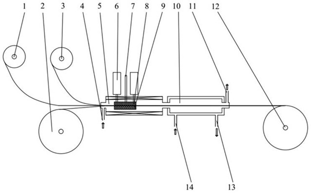
Figure 1. Continuous pressure-brazing line for joining the BAg72Cu filler strip (1), profiled copper strip (2), and tungsten strip (3), followed by cooling and strip take-up.
For applications in which the contact will be welded to a copper carrier, Fudar Alloy's process can include a second continuous stage before final shaping and cutting. After the copper underside of the bonded strip is cleaned, a lower-melting filler strip of matching width is aligned with the copper surface and continuously fused onto it. The filler strip has a specified thickness of 0.02–0.10 mm and is fused at 650–850 °C in a non-oxidizing atmosphere.
Suitable secondary filler materials include BAg15CuP, BAg45CuZn, BAg60CuSn, BAg34CuZnSn, and BAg40CuZnSnNi. The added layer creates a weldable interface on the copper side, allowing the finished contact to be welded to the carrier instead of riveted. Eliminating the riveting step can reduce gaps at the attachment interface and lower the risk of deforming or cracking the tungsten during assembly.
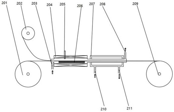
Figure 2. Continuous process for applying the BAg15CuP filler strip (202) to the copper side of the bonded tungsten-copper profile (201).
Fudar Alloy demonstrated the continuous strip-brazing process through two representative contact configurations.
T-Shaped Contact for Automotive Horns
The first design combines a 4 mm-wide, 0.5 mm-thick tungsten strip with a 4 mm-wide BAg72Cu filler strip measuring 0.05 ± 0.01 mm in thickness. The T-shaped TU1 copper profile measures 4 mm × 0.5 mm with a 2 mm × 1 mm stem.
After cleaning, the three strips are continuously brazed using high-frequency heating at 805 ± 5 °C under 100 N in a protective hydrogen–nitrogen atmosphere produced by dissociated ammonia. The bonded strip is then drawn to its final profile, sawn into 4 mm lengths, and riveted to copper carriers for automotive horn applications.
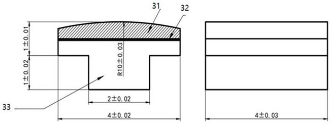
Figure 3. Cross-section of the T-shaped automotive horn contact: tungsten working layer (31), BAg72Cu brazing layer (32), and copper support (33).
Contact Design with a Secondary Attachment Layer
The second design uses a 3 mm-wide, 0.5 mm-thick tungsten strip, a 3 mm-wide BAg72Cu strip measuring 0.05 ± 0.01 mm in thickness, and a ribbed TU1 copper profile measuring 3 mm × 0.5 mm. The primary brazing stage uses the same high-frequency heating, 100 N pressure, 805 ± 5 °C temperature, and protective atmosphere as the first design.
A BAg15CuP strip measuring 0.03 ± 0.01 mm in thickness is then fused to the copper side at 750 ± 3 °C in a protective atmosphere produced by dissociated ammonia. The gas flow is maintained at 1.5 m³/h, while the strip travels at 0.9–1.0 m/min. The composite strip is profile-rolled to 3 mm × 1 mm, cut by punching into 3 mm lengths, and spot-welded to copper components for use in automotive horn contacts or arc contacts in LED lamps.
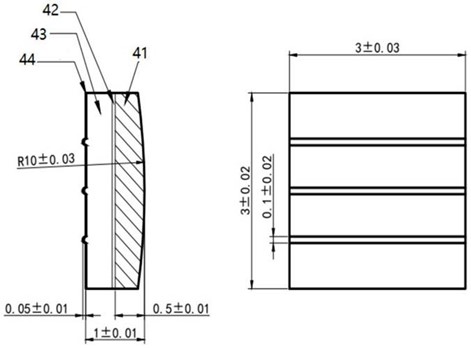
Figure 4. Cross-section of the contact with a secondary attachment layer: tungsten working layer (41), BAg72Cu brazing layer (42), copper support (43), and BAg15CuP attachment layer (44).
In the two configurations, electrical endurance exceeded 100,000 operations, with a thickness tolerance of ±0.01 mm and a width tolerance of ±0.02 mm. The endurance result relates to the specific materials, structures, and test conditions used for these configurations. By comparison, the conventional single-piece furnace-brazing process is described as achieving dimensional accuracy within ±0.05 mm.
Controlling alignment and shaping at the strip stage makes the process well suited to automated, high-volume production. The copper support can be formed as a T-profile or designed with multiple ribs, grooves, or patterned features to suit different riveting and welding methods. An optional attachment layer can also support welded assembly, allowing the contact structure and joining method to be matched to specific application requirements.
To discuss tungsten-copper contact structures, attachment methods, or application requirements, contact the Fudar Alloy team.
Please fill out the form below. Our sales team is ready to assist you with any questions or inquiries.